
In today's rapidly advancing technological landscape, LiDAR stands out as a pivotal tool for various applications, from forestry management to infrastructure inspection. Dive into the world of LiDAR with DJI Enterprise's comprehensive guide. From foundational principles to real-world applications, this booklet equips readers with essential knowledge on LiDAR technology and its transformative potential.
Introduction and Principles of the LiDAR Technology
What is LiDAR?
LiDAR, which stands for Light Detection and Ranging, is a remote sensing technology that uses rapid laser pulses to map out the surface of the target. By sending out a laser beam and measuring the time it takes for the light to reflect back from objects, LiDAR creates detailed three-dimensional point maps.
Imagine you're in a completely dark room with a flashlight. If you point the flashlight at various objects, the light will bounce back, and by seeing that light, you can get an idea of where things are and how far away they are. The more times you shine your light and from different angles, the better idea you'll get about the layout of the room. LiDAR works similarly but instead of using visible light like a flashlight, it uses invisible laser light. Here's how it functions:
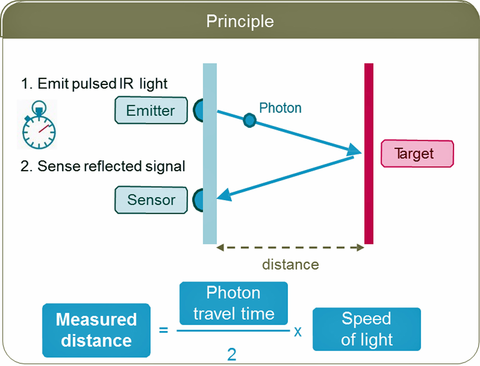
1. Emission: LiDAR device sends out a rapid pulse of laser light towards an object.
2. Reflection: The light then reflects off the object and returns to the LiDAR sensor.
3. Detection: The device measures the time it took for the light to return. Since the speed of light is a constant, this duration time can be used to calculate the distance between the LiDAR sensor and the target object.
LiDAR vs. Photogrammetry
The LiDAR system measures data, whereas the Photogrammetry system calculates it. This key difference makes them better suited for different applications. LiDAR uses laser pulses to measure reality, making it ideal for applications that require absolute data certainty. LiDAR can penetrate through vegetation and is not affected by lighting conditions, making it a great option for mapping forests or other areas with dense vegetation cover. LiDAR is also useful for creating accurate terrain models and topographic maps.
Photogrammetry uses cameras to capture overlapping images of an area, which are then stitched together to create a 3D model or ortho map. It is less expensive than LiDAR and can be used with off-the-shelf hardware like any drones and cameras. This makes it useful for creating highly detailed models of buildings and infrastructure, as well as high-resolution orthomaps for inspection and monitoring applications.
| Aspect | Photogrammetry | LiDAR |
|---|---|---|
| Definition | A technique of obtaining measurements and 3D models from photographs. | A remote sensing method using laser light to measure distances, and generate precise 3D models of the Earth's surface. |
| Accuracy | High accuracy in well-lit and clear conditions after apply GCPs under RTK. | Accuracy rely on the initial POS state, not dependent on lighting conditions. |
| Cost | Generally lower cost, more affordable for small-scale projects. | Higher cost due to sophisticated equipment and processing requirements. |
| Terrain Handling | Performs well in urban environments and clear landscapes. | Excellent in various terrains, including dense vegetation and urban landscapes. |
| Data Processing | Time-consuming processing, especially for large datasets. | Processing is faster because the data is captured in spatial coordinates format natively. |
| Light Conditions | Requires good lighting for optimal results. | Effective in any lighting conditions, including night. |
| Vegetation Penetration | Struggles with dense vegetation. | Capable of penetrating dense vegetation to reach the ground. |
| Weather Dependency | Performance can be affected by weather conditions like clouds and rain. | Less affected by weather conditions. |
| Spatial Resolution | High spatial resolution for surface details. | Lower spatial resolution compared to photogrammetry. |
| Application | Ideal for cultural heritage documentation, small-scale mapping, and architecture. | Best suited for large-scale topographic mapping, forestry, and urban planning. |
What are the Components of an Integrated Airborne LiDAR System?
Hardware Components
LiDAR System
- LiDAR Module: The most important component of the LiDAR system, the laser module generates a pulsed laser beam that is directed at the target surface. The laser module is made up of multiple components, including the laser light source, receiver, optical components, and electronic controller.
- Laser Light Source: It generates short pulses of laser light that are used to measure the distance between the LiDAR sensor and objects in the environment.
- Receiver: It detects the reflected laser light and converts it into an electronic signal that can be processed by the LiDAR system.
- Optical Components: These components are responsible for directing and focusing the laser beam toward the target surface and collecting the reflected light.
- Electronic Controller: It controls the timing and duration of the laser pulses and processes the signals from the receiver.
- GNSS (Global Navigation Satellite System) receiver is used to provide accurate georeferencing for scanned LiDAR results. Most UAV LiDAR systems either use their own individual GNSS system for logging satellite data for georeferencing and post-processing or are integrated with DJI PSDK and use the GNSS system from the drone system.
- IMU (Inertial Measurement Unit) is a device that measures the acceleration and angular rate of a LiDAR system. By integrating these measurements over time, the IMU can determine the position, velocity, and attitude of the LiDAR system in three-dimensional space. This information is used to correct for any motion or vibrations of the LiDAR system during the data collection process.
- INS (Inertial Navigation System) uses the raw data from an IMU and integrates it to provide position, velocity, and orientation information of an object relative to a known starting point, orientation, and velocity. INS takes the IMU data and integrates it with GNSS positioning information to provide a continuous estimation of the position and orientation of the LiDAR sensor during the data capture.
UAV System
- UAV or unmanned aerial vehicle is used to fly the LiDAR system over the area being surveyed, and it can be equipped with its own GNSS and RTK/PPK system for accurate georeferencing of the LiDAR system.
Software Components
- Flight Mission Planning Software is utilized to plan the flight path of a drone equipped with a LiDAR system. This software enables the user to define an area to be surveyed and then automatically generates a waypoint-based flight route. The user can adjust UAV system parameters and sensor actions for the autonomous waypoint flight. The software then generates a flight path that efficiently covers the area and collects the necessary data for the LiDAR system. This data can be used to create detailed 3D maps or models of the surveyed area.
- Flight Monitoring and Control Software allows the user to monitor the flight path and status of the UAV and LiDAR system in real-time during data collection. The software can display various parameters such as altitude, speed, and battery level. This information is crucial for ensuring the safety of the UAV and collecting high-quality LiDAR data. Additionally, the flight monitoring software can alert the user in case of any issues or malfunctions during the flight.
- Raw Point Cloud Processing Software is OEM software developed by sensor manufacturers. It is used to process raw LiDAR data collected from all system components and output the LiDAR data into a manipulable format such as LAS/LAZ for further use.
- Point Cloud Processing Software refers to computer programs that are designed to manipulate and analyze point cloud data. Depending on the application, point cloud processing software can be used for various tasks such as creating drawings, performing measurements, extracting surfaces, classification, and more.
.png?width=715&height=303&name=Untitled%20(1).png)
Key Terminologies and Knowledge
Object Surface Reflectivity
- Different object surfaces have varying rates of reflectivity.
- Most object surfaces have a reflectivity of above 10%.
- Water is a strong absorber, and a typical LiDAR laser with a wavelength of 905nm will be absorbed directly. Unless the LiDAR is of the bathymetric type and the laser wavelength is shorter, it will not penetrate water.
Here are some examples of surface reflectivity rates:
- Fresh asphalt: 4-7%
- Dry grass: 15-20%
- Forest canopy: 5-20%
- Wet concrete: 30-50%
- Snow: 60-90%
.png?width=643&height=376&name=Untitled%20(2).png)
Point cloud colorized by base on surface reflectivity (Red is high, blue is low)
LiDAR Scanning Methods
By changing the rotation method inside the LiDAR sensor, the LiDAR system can achieve two different mechanical scanning modes: repetitive scan and non-repetitive scan.
Repetitive Scanning Method
Repeated scanning only covers the horizontal FOV (70.4°×4.5°)
Advantage: In mobile mapping, objects are only scanned for a very short period of time, because the inertial navigation accuracy drift is very small in a short period of time, so the scanned model is relatively more accurate.
Disadvantage: The vertical FOV is very small and there is almost no vertical surface information. If vertical surface information is required, at least two flight paths need to be planned to compensate for the loss of vertical FOV.
Application: For scenarios with relatively mild terrain and high accuracy requirements, such as terrain measurement, general DEM/DSM generation.
*It is recommended to use repetitive scan in surveying to ensure point cloud accuracy.
: For scenarios with relatively mild terrain and high accuracy requirements, such as terrain measurement, general DEM/DSM generation.
*It is recommended to use repetitive scan in surveying to ensure point cloud accuracy.
Repetitive Scan Animation (Top-down View)
Non-repetitive Scanning Method
Non-repetitive scanning can quickly cover the entire FOV (70.4°×77.2°)
Advantages: Provides full FOV coverage, can perform vertical scanning, and obtains good vertical information from a single scan without setting a gimbal angle.
Disadvantage: In mobile mapping, objects are scanned at different positions and times, relying on consistent inertial navigation accuracy. If the accuracy of inertial navigation drifts over time, the accuracy of the model will decrease. This results in blurred or duplicated objects, thicker point clouds, and thicker wires. This effect is particularly pronounced in non-repetitive scans, which have a larger field of view.
Application: Suitable for scenarios with relatively low accuracy requirements, high efficiency requirements, and complete elevation information requirements, such as urban 3D modeling, complex three-dimensional structure modeling, power line inspection, emergency rapid mapping, etc.
*In the scenario of power line inspection, if single-line flight is chosen, it is recommended to use the non-repetitive scanning method.
Non-repetitive Scan Animation (Top-down View)
Wavelength
LiDAR systems use lasers to emit pulses of light, with the wavelength of the laser determining the characteristics of the pulse. The wavelength of the laser affects the LiDAR system's ability to penetrate various materials and the types of reflections it can detect. Following are two common LiDAR types and their corresponding wavelength range
- Near-infrared (NIR) LiDAR typically use lasers with wavelengths between 800 and 1,000 nanometers. NIR LiDAR systems are better at penetrating vegetation and can detect multiple returns from a single pulse, making them ideal for forestry applications. However, these LiDAR systems cannot penetrate water and are not suitable for bathymetric applications.
- Bathymetric LiDAR use shorter wavelengths of light in the green and blue spectrum to penetrate water and measure the depth of the seafloor. The green laser light with a wavelength of 532 nm is the most commonly used for bathymetric LiDAR as it penetrates water better than other wavelengths. The blue laser light with a wavelength of 445 nm is also used in some bathymetric LiDAR systems as it provides better penetration in clear water conditions. The bathymetric LiDAR systems are used for applications such as seafloor mapping, coastal zone management, and underwater infrastructure inspection.
Detection Range
Detection range refers to the maximum distance at which a LiDAR system can accurately detect and measure objects. Several factors affect the detection range of a LiDAR system, including the power and wavelength of the laser, the sensitivity of the receiver, and the reflectivity of the objects being scanned. Typically, the detection range specification is provided with the target surface reflectivity or environmental conditions as a reference.
.png?width=638&height=234&name=Untitled%20(14).png)
It's worth noting that the maximum detection range specified by LiDAR manufacturers is usually tested based on a reflectivity of 90%, which is not meaningful for practical use. The detection distance at a reflectivity of 10% has more practical meaning since it applies to most surfaces.
Longer detection range is desirable for LiDAR systems since it allows for greater coverage area and more comprehensive data collection.
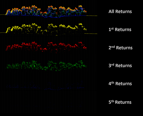
Multiple Returns
The laser in a LiDAR system sends out pulses. When these pulses hit obstacles, they reflect back. Because the light doesn't get fully blocked, it continues on, bouncing back each time it hits something. This makes it seem like LiDAR can "see through" vegetation. But what's really happening is that LiDAR is detecting the ground and tree canopy by looking through gaps between leaves.
- First return: This is the first reflection that the sensor captures, often from the topmost object in the path of the laser pulse (like treetops or the tops of buildings).
- Intermediate returns: These are reflections from objects between the topmost object and the ground (like branches or windows).
- Last return: This is usually the reflection from the ground or the base of an object.
*Rain or smog in the air can cause interference and noise in the LiDAR data. In these situations, using the strongest “single return” is advised.
Related Applications
The ability to detect multiple returns allows for a more detailed understanding of the object. For instance:
- Vegetation Extraction: Segmenting individual plants, counting them, calculating biomass, and analyzing vegetation parameters.
- Topographic Mapping: Extracting DEM (Digital Elevation Model) from DSM (Digital Surface Model) for terrain analysis.
- Power Line Modeling: Power lines often overlap, and the multi-return capability can measure multiple layers of wires in one go, reducing missing data due to obstructions.
Beam Divergence
Beam divergence refers to the spreading out or broadening of a laser beam over distance. Beam divergence represents the angle at which the laser beam spreads as it travels from the LiDAR sensor and moves further from its point of origin.
Essentially, a smaller beam divergence means the laser remains more focused over longer distances, while a larger beam divergence means the laser will spread out more as it travels.
Impact on Canopy Penetration
In environments like forests, a smaller beam divergence (more focused beam) is typically more effective at penetrating the canopy and reaching the ground below. This is because a more concentrated laser beam can more easily find gaps between leaves and branches, resulting in better ground point detection. On the other hand, a laser with higher beam divergence might scatter off the canopy more and may not reach the forest floor as effectively.
.png?width=771&height=507&name=Untitled%20(6).png)
Impact on Point Density and Resolution
While a more focused beam (smaller divergence) can give more accurate and higher resolution results, a beam with larger divergence may cover a larger area with each pulse, leading to potentially lower point density and resolution at the target.Impact on Point Density and Resolution
Impact on Range and Energy Distribution
Lasers with smaller beam divergence maintain their energy concentration over longer distances. This is crucial for LiDAR systems that need to operate over long ranges. As the beam diverges more, the energy gets spread over a larger area, potentially decreasing the return signal's strength, especially at longer distances.
Atmospheric Interaction
Beam divergence can also play a role in how the laser interacts with particles in the atmosphere like dust, fog, or rain. A laser beam with a larger divergence might scatter more due to interactions with these particles, which can reduce the effective range and accuracy of the LiDAR system in certain conditions.
Sampling Rate
The sampling rate refers to the number of points collected by a LiDAR system in a given period. It is measured in hertz (Hz). A higher sampling rate means that more points are collected per second, resulting in a denser point cloud.
However, a higher sampling rate also means that more data is being collected, which can lead to larger file sizes and longer post-processing times. Therefore, the sampling rate of a LiDAR system should be carefully chosen based on the specific density needs of the project.
It is important to note that the sampling rate alone does not determine the accuracy of the LiDAR data. Other factors, such as the laser beam divergence and the accuracy of the IMU and GPS, also play a significant role in determining the accuracy of the data.
IMU Calibration
LiDAR accuracy is closely tied to the IMU's precision. When a drone flies at a steady pace, the IMU might lose its accuracy. Hence, most airborne LiDAR systems require IMU calibration before, during, and after the flight. If the IMU is not calibrated, it can result in inaccurate data, affecting subsequent analysis and applications that rely on the LiDAR data.
There are two common methods to calibrate the IMU during drone flight: the "figure-eight" and "speeding up-slowing down" calibrations. Both manual and automatic calibration methods provide the same outcomes.
DJI's integrated LiDAR system uses the "speeding up-slowing down" calibration method, and the IMU calibration process is automatically integrated when operating any mission flight. When flying the DJI LiDAR system manually, the DJI Pilot app will remind the user to recalibrate the IMU after a period of flight time.
.png?width=596&height=374&name=Untitled%20(7).png)
Performance Affecting Factors
Efficiency and penetration rate can be affected by various factors in LiDAR technology. Beam divergence and multiple returns play a role in penetration, while IMU calibration affects accuracy. Strip alignment impacts precision, and different scanning methods affect vertical scan coverage and density. Flight speed and sampling rate impact density as well.
Factors Affecting Density:
- Sampling Rate: A higher pulse repetition frequency (PRF) or sampling rate can result in a higher point density, assuming other factors like flight speed and altitude remain constant.
- Flight Altitude: Flying at a lower altitude usually results in higher point density because the laser pulses have a smaller footprint on the ground.
- Overlap: Surveying with overlapping flight lines can increase point density in the overlapping regions.
- Terrain & Vegetation: Features like dense forests can result in multiple returns from a single laser pulse, potentially increasing the effective density in those areas.
- Flight Speed: A slower flight speed allows for a higher point density since the LiDAR sensor has more time to send out laser pulses and detect their returns.
Raw LiDAR Data Processing
Point Cloud Density
Density describes the number of LiDAR points collected per unit area. It's often expressed as points per square meter (pts/m^2). For instance, a density of 10 pts/m^2 means that, on average, there are 10 LiDAR return points in every square meter of the surveyed area.
Different vertical industries have varying requirements for point cloud density:
- Surveying & Mapping: For 1:500 scale maps, the required point cloud density is ≥16 points/square meter.
- Power Line Inspection: For detailed tree barrier analysis or thorough inspections, transmission lines generally require at least 25 points/square meter. Some specifications demand even better densities, typically ranging from 50 up to 250 points/square meter.
- Forestry Survey: A point cloud density of at least 20 points/square meter is necessary to meet the demands of individual tree segmentation.
.png?width=682&height=380&name=Untitled%20(8).png)
Raw point cloud processing software usually also has a feature to adjust the point density
LiDAR Elevation Accuracy Verification
Verifying the accuracy of LiDAR data using elevation checkpoints is a common method to ensure that the derived digital elevation models (DEMs) or digital terrain models (DTMs) are accurate representations of the ground.
Principles for Setting Up Elevation Checkpoints:
- Checkpoints should be evenly distributed and conspicuously positioned.
- Avoid placing them in areas where flight strips overlap or where there are sudden elevation changes.
- Checkpoints should be situated on exposed and flat surfaces.
- The elevation reference for the checkpoints should match the elevation reference of the laser point cloud.
Guidelines for Elevation Checkpoints:
- Spread checkpoints out evenly in clear spots.
- Don't put them where flight paths cross or where the ground level changes quickly.
- They should be on open, level ground.
- Make sure their height matches the height used in the LiDAR data.
LAS Point Cloud Format
The LAS format was developed by the American Society for Photogrammetry and Remote Sensing (ASPRS) to enable the exchange of LiDAR point cloud data between different companies and agencies. LAS format is a standardized file format for storing and exchanging LiDAR point cloud data, containing information about each point's location, intensity, classification, and other attributes. It is also the deliverable outcome from the DJI LiDAR systems.
The LAS format for point cloud data includes information such as the three-dimensional coordinates of points, RGB colors, reflectance, GPS time, number of returns, and which return a point is.
LAS file versioning can be an issue when trying to read or write a file. It is important to ensure that the LAS file version being used is compatible with the third-party software being used to process it. Some third-party software may not be able to read or write certain versions of LAS files. If a compatibility issue arises, it may be necessary to use a different version of the LAS file or to find different third-party software that supports the version being used. DJI Terra exports the LiDAR point cloud data in the LAS version 1.2 format, which is a highly compatible version of the LAS file.
Point Cloud Colorization
Colorized point clouds can provide additional context to users, making it easier to interpret and understand the data. For example, a building and a tree might have similar structural shapes in certain aspects, but color can instantly differentiate them.
Most aerial LiDAR systems are equipped with RGB cameras that capture high-resolution imagery simultaneously with LiDAR data collection. These images can then be used to assign color values to the corresponding LiDAR points.
Colorization Benefits:
- Visual Appeal: Colorized point clouds are more visually appealing and understandable than grayscale ones.
- Enhanced Analysis: Color can provide additional information, such as helping in vegetation analysis by distinguishing between different types of plants or in urban mapping to differentiate between various infrastructures.
- Integration with Other Datasets: A colorized point cloud can be easily integrated with other geospatial datasets, offering a comprehensive view of a surveyed area.
- Integration with Other Datasets: A colorized point cloud can be easily integrated with other geospatial datasets, offering a comprehensive view of a surveyed area.
- Additional Photogrammetry Process: RGB photos can also be used for photogrammetry processing, in addition to point cloud coloring.
.png?width=788&height=456&name=Untitled%20(9).png)
Flight Trajectory
Trajectory refers to the path flown by a UAV equipped with a LiDAR system during data collection. The trajectory is a critical factor in LiDAR data processing because it provides location data for every point in the point cloud. Trajectory information is necessary to accurately georeferenced LiDAR data and produce accurate 3D models of the surveyed area.
SBET refers to the Smoothed Best Estimate of Trajectory. It is a commonly used post-processed file format that contains highly accurate GPS and IMU data. This format of the trajectory file can be correlated with the LAS point cloud for further postprocessing. The postprocessing trajectory file of the LiDAR mission is usually generated automatically along with the deliverable point cloud LAS file. It can be imported into third-party software for trajectory display.
.png?width=807&height=359&name=Untitled%20(10).png)
Strip Adjustment
Strip adjustment is a procedure to rectify systematic errors and misalignments in airborne LiDAR data, especially when gathered over multiple flight strips. When a terrain is surveyed using airborne LiDAR, the area is typically covered in multiple overlapping strips or flight paths. The overlap is intentional to ensure coverage continuity and to facilitate error correction.
During LiDAR data acquisition, several factors can introduce errors in the data:
- Sensor Drift: Over time, the IMU and GPS may experience slight drifts in their readings.
- Flight Dynamics: Turbulence, rapid altitude changes, and changes in aircraft orientation can influence the captured data.
Because of these factors, adjacent flight strips can sometimes display vertical or horizontal mismatches. If not corrected, these errors can affect subsequent analysis and applications that rely on the LiDAR data.
Benefits of Strip Adjustment:
- Improved Data Consistency: Reduces mismatches and ensures continuity across adjacent flight strips.
- Higher Quality Derivatives: The quality of derived products such as Digital Elevation Models (DEMs) and Digital Surface Models (DSMs) is enhanced.
- Reliability: Increases confidence in the accuracy of the LiDAR dataset, making it more reliable for various applications, from topographic mapping to forestry.
Raw LiDAR Data Processing with DJI Terra software
DJI Terra software is the only supported software used to process and export the raw LiDAR point cloud data collected from a DJI LiDAR system in the universal LAS format.
Key LiDAR Processing Features
DJI Terra is a free-to-begin LiDAR raw data processing software that enables the creation of LAS point cloud deliverables from the LiDAR Raw data. It is also packed with additional features.
Adjust Point Cloud Density
Refers to the number of points collected per unit area. This feature allows for adjusting the point density to meet specific industry demands.
Optimize Point Cloud Accuracy
This feature uses the strip Locality Preserving Projections (LPP) algorithm to minimize the common layering phenomenon of point clouds, making the point clouds align on a thinner layer to improve the accuracy of the point cloud model.
Smooth Point Cloud
This feature refines the point cloud by filtering out noise and reducing the impact of errors to create a smoother visual representation.
Ground Point Classification
Used to distinguish ground points from other objects in the point cloud to generate a Digital Elevation Model (DEM).
Generate DEM
This feature generates a GeoTiFF formatted Digital Elevation Model (DEM) from the classified ground point cloud.
Vertical Accuracy Check and Shift
Verifies the accuracy of LiDAR data using elevation checkpoints to ensure that the derived DEMs or DTMs are accurate representations of the ground.
Coordinate System Transformation
Allows for easy transformation of local projected or geodetic coordinate systems for different mapping and surveying projects all over the world.
.png?width=770&height=446&name=Untitled%20(12).png)
Airborne LiDAR Applications
Forestry Management
LiDAR has a wide range of applications in forestry management. It can estimate tree heights, measure biomass, and map forest structure. By using LiDAR, forest managers can obtain detailed information about the forest canopy, which is difficult to obtain using traditional survey methods. One of the key advantages of LiDAR is its ability to detect multiple returns from a single laser pulse, allowing it to "see through" vegetation and accurately map the ground surface. This capability makes LiDAR particularly useful for estimating ground elevation and identifying changes in forest cover over time, which can be helpful for tracking deforestation and reforestation efforts. Additionally, LiDAR can aid in the development of forest inventories, which are critical for sustainable forest management.
Volumetric Measurement
LiDAR technology can provide accurate measurements for volumetry calculations, which is useful for industries such as mining, construction, and forestry. By using LiDAR point cloud data, it is possible to calculate the volume of a stockpile or the amount of material removed from a site accurately. This information can be used for inventory management, cost control, and resource planning.
Topographic Survey
LiDAR is an effective tool of course for topographic surveys as it can accurately map out the shape and features of the Earth's surface. Unlike photogrammetry, LiDAR can penetrate through the canopy and capture accurate ground surface measurements, even in areas with dense vegetation cover. This is because LiDAR uses laser pulses to detect the ground and tree canopy by looking through gaps between leaves, resulting in better ground point detection.
Archaeological Research
Airborne LiDAR can be easily used in archaeological research to map out massive, hard-to-reach areas and uncover hidden structures on the surface. The LiDAR sensor can penetrate vegetation and capture high-resolution data, making it possible to identify structures that would be difficult or impossible to see from the ground. This can help archaeologists better understand the layout of ancient cities and settlements and gain insight into past human activity.
Powerline Inspection
LiDAR technology can be used to inspect power lines, which can be challenging due to the height and location of the lines. By using LiDAR point cloud data, it is possible to create a detailed map of power lines and their surroundings. This can help identify potential issues such as vegetation growth or sagging lines, which can cause power outages or safety hazards.
Infrastructure Inspection
With LiDAR's ability to detect small imperfections and cracks, many are using the technology to scan roadways and building/bridge facades. This can help alert project managers to issues with structures that need to be resolved immediately. With façade capture specifically, it's important to implement a LiDAR system that's gimblized to face the facade.


-3.png?width=300&name=Insight%20blog%20featured%20image%201140X660%20(2)-3.png)