
Post-processed kinematic (PPK) is a method of using Global Navigation Satellite System (GNSS) data to accurately determine the position and trajectory of a rover/drone. PPK involves collecting raw GNSS data from a drone, along with information about the position and trajectory of nearby reference stations, and then processing the data after the fact to improve the accuracy of the position and trajectory information.
Post-Processed Kinematic (PPK) Process Introduction
PPK is commonly used in applications such as surveying, mapping, and precision agriculture, where high-accuracy positioning is critical. Unlike Real-Time Kinematic (RTK) positioning, which requires a real-time wireless connection to reference stations, PPK can be done after the fact, allowing for greater flexibility in data collection.
The post-processing of GNSS data involves using specialized software to process the raw data collected by the receiver and compare it with data from nearby reference stations to determine the precise location of the drone at a given point in time. This process can improve the accuracy of the position and trajectory information by correcting for errors introduced by factors such as atmospheric conditions and satellite orbit deviations.
While both RTK and PPK positioning can be used for drone mapping applications, there are some advantages of using PPK over RTK:
|
Pros |
Cons |
|
|
RTK |
Real-Time Feedback: With RTK, real-time feedback is available during the mission, which can make it easier to identify and address issues as they arise. Fast Data Processing: RTK data can be processed quickly, which allows for a faster turnaround time for delivering the final product. User-Friendly: RTK is typically easier to use than PPK and requires less skill to set up and operate. |
Lower Accuracy: RTK accuracy can be affected by communication delays and interruptions, making it less accurate than PPK. Communication Dependency: RTK requires real-time communication with a reference station during the mission, which can be challenging in remote or rural areas with limited or no cellular coverage when using RTK via the NTRIP protocol. Higher Costs: RTK can be more expensive than PPK due to the need for additional RTK modules or NTRIP service subscription fees. |
|
PPK |
No Real-Time Communication Required: RTK requires real-time communication between the drone and the ground station to receive correction data from the reference station. PPK, on the other hand, does not require real-time communication as the correction data is applied later during post-processing. Greater Flexibility: With PPK, the drone can fly the mission and collect data, and the post-processing can be done later, providing greater flexibility for data collection, especially in areas with limited or no cellular coverage. Higher Accuracy: While both RTK and PPK can provide high accuracy, PPK can offer even higher accuracy as it is not subject to any potential communication delays or disruptions during data collection. PPK can also use more reference stations during post-processing, which can further improve the accuracy. Reduced Costs: PPK can be less expensive than RTK because it does not require real-time communication, which can require additional equipment and subscription fees. |
Longer Post-Processing Time: PPK requires post-processing of data, which can take time and delay the delivery of the final product. Minimal Flight Duration Requirement: To achieve accurate positioning data, it is necessary to capture sufficient GNSS data points during the flight. This means that the drone must fly for a certain duration and distance to capture enough data points for PPK processing. The exact duration and distance required will depend on various factors such as the GNSS receiver used, the quality of the reference station data, and the flying environment. Generally, a minimum flight duration of 10 minutes is recommended to capture enough GNSS data points for accurate PPK processing. However, this may vary depending on the specific requirements of the mapping project and the quality of the GNSS data collected. |
The selection of PPK or RTK for a mapping project ultimately depends on specific requirements, including flexibility, cost, and mission scale. Although both methods have their advantages and disadvantages, DJI Enterprise RTK drones always record satellite observation data. This ensures that even if an unstable cellular environment interrupts real-time communication during an RTK flight, the user can still retrieve base station data and use the PPK method as backup to output centimeter-level accurate data.
PPK Process Workflow
Conducting a PPK (Post-Processed Kinematic) workflow using drone image data may initially seem complex, but it's a straightforward process when approached with proper planning and attention to detail. The workflow consists of several key steps, which are explained below:
- Preparation and Planning: Before collecting drone data, it’s essential to plan your mission thoroughly. This includes ensuring that the flight duration is adequate within the flight mission planning software. Proper mission planning guarantees that you collect enough data for accurate PPK processing.
- Collecting Drone Data: Once you have planned the mission, it is time to collect the drone image data and the corresponding GNSS data from the drone receiver during the flight. The GNSS data should include the raw satellite navigation system data, as well as timestamp information.
- Collecting Reference Data: In addition to drone data, you must collect reference data from nearby GNSS reference stations, such as CORS (Continuously Operating Reference Station) or other ground-based receivers. The reference data should match the GNSS signals and timing information of the drone’s data. Accurate reference data is crucial for ensuring the precision of the PPK process.
- Data Alignment and PPK Processing: Once you’ve gathered all necessary data, the next step is aligning the drone image data with the GNSS data based on timing. PPK process software can synchronize the timing information between the images and GNSS data points. After aligning the data, use PPK software or online services to process it. This step leverages GNSS data from both the drone receiver and reference stations to calculate the precise positioning information for each captured image.
- POS Data Overwrite: Ensure that the new POS (Position and Orientation System) data is correctly imported into your photogrammetry process software. This is a critical step, as the accuracy of the photogrammetric models depends heavily on the quality of the input data. Double-check the compatibility of the POS data with your software to confirm that it is correctly overwritten.
Step 1. Preparation and Planning
Not all DJI Enterprise systems are capable of outputting the necessary data for the PPK process. This is because the drone must be equipped with specific hardware components that enable the recording of raw GPS observation data.
Before getting started, ensure that the system you're using supports PPK functionality. Below is a list of compatible drones and payloads that meet the required specifications.
|
UAV and Payload Hardware (One of the options provided) |
Matrice M350 /Matrice 300 RTK + Zenmuse P1 Matrice M350 /Matrice 300 RTK + Zenmuse L1 /Zenmuse L2 Mavic 3 Enterprise + RTK Module Mavic 3 Multispectral + RTK Module |
|
Flight Mission Planning Software |
DJI Pilot 2 app / DJI FlightHub 2 |
|
Source for Base Receiver Independent Exchange (RINEX) file and Navigation files |
DJI D-RTK 3 Multifunctional Station Third-party Base Station NGS CORS (Online) |
| PPK Process Software |
Third-party PPK Software (e.g., Emlid Studio, REDcatch, Propeller Aero) |
| Photogrammetry Software |
DJI Terra |
Before flying your drone, it is important to properly configure your DJI Pilot 2 app. Here are a few tips to ensure a successful flight:
Tip 1: Enable the “Mechanical Shutter” option and disable the “Dewarping” option if available.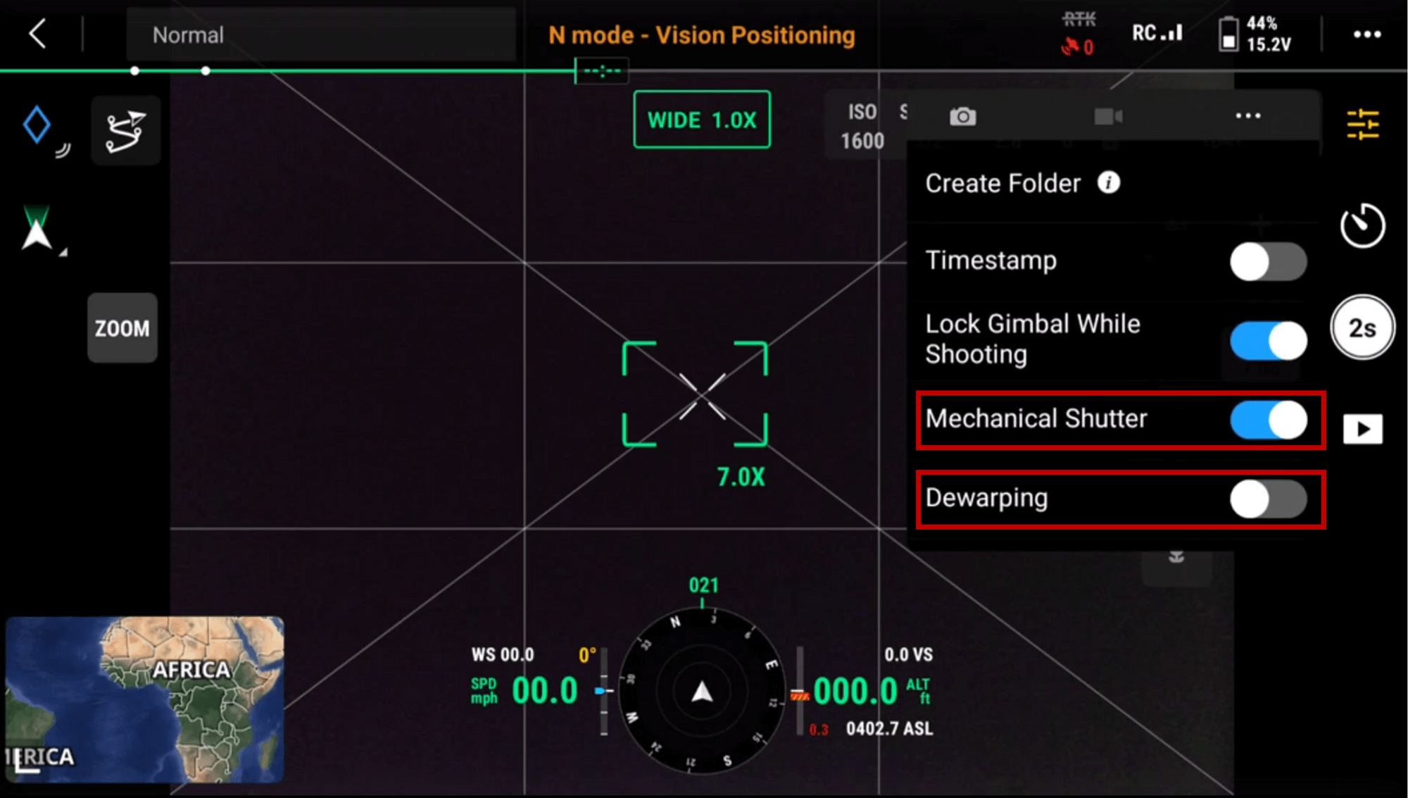
Pilot 2 app - Mechanical Shutter and Dewarping Settings
Tip 2: PPK files are typically generated automatically when data is collected using automated missions. However, in rare situations where you need to manually initiate PPK recording, you can do so by navigating to the camera settings and selecting the “Create Folder” option. This will create a new mission directory, start logging all relevant PPK files, and store them along with any captured photos or LiDAR data.
Tip 3: It is important to note that the PPK process requires post-processing of data, which may take time and delay the delivery of the final product. Additionally, achieving accurate positioning data with PPK requires capturing sufficient GNSS data points during the flight. The exact duration and distance required will depend on various factors such as the GNSS receiver used, the quality of the reference station data, and the flying environment. Generally, it is recommended to fly for a minimum of 15 minutes to capture enough GNSS data points for accurate PPK processing. Within the Pilot app, you can check the estimated mission flight time under the mission overview drop down tab.
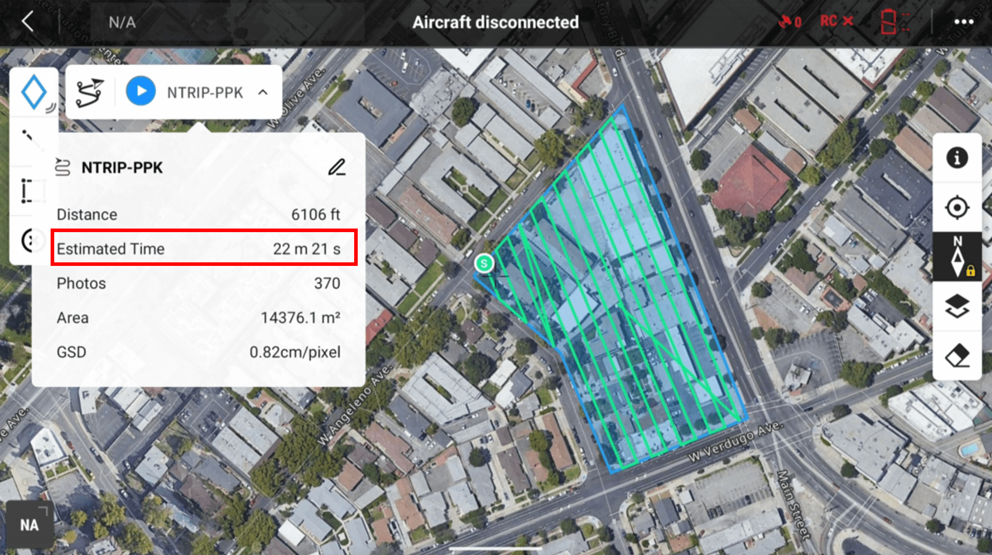
Pilot 2 app- Estimated Flight Time
Step 2. Collecting Drone Data
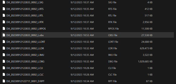
To properly process with the PPK method, preparing drone data is essential. for photogrammetry drone data, In addition to raw images, there are four additional files that are required from the image folder (Depends on the UAV or different payload used, these file name and structure may sightly differ, but overall similar):
.navfile is the satellite ephemeris file.obsfile is a RINEX (Receiver Independent Exchange) formatted satellite observation file generated in real time through decoding..binor.rtkfile contains satellite observation and ephemeris data from the mobile station in RTCM (Radio Technical Commission for Maritime) format..mrkfile is an ASCII file that stores image exposure timestamps in plain text format.
The drone’s satellite observation data contains raw GPS measurements, which are essential for achieving high-accuracy positioning. This data is used to correct for GPS signal errors caused by factors such as atmospheric conditions, satellite geometry, and clock drift.
Equally important, the image timestamp file is critical for accurate image POS (Position and Orientation System)correction. It records the exact time each image was captured, enabling precise synchronization between the imagery and the satellite observation data. Without this timing information, accurately aligning the image data with the GPS measurements becomes extremely difficult, leading to a significant reduction in the accuracy of the final results.
Without both the satellite observation data and the timestamp file, the PPK (Post-Processed Kinematic) process cannot be performed. It is essential to ensure that these files are properly collected and processed in order to PPK process.
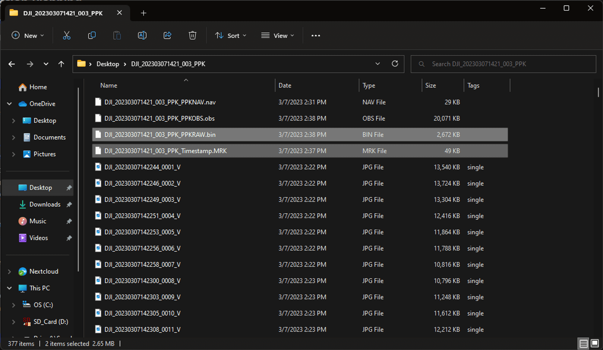
Photogrammetry Raw Data with PPK files
Step 3. Collecting Reference Data
To perform PPK (Post-Processed Kinematic) processing using a base station for reference data, you typically need two types of files related to GNSS (Global Navigation Satellite System) data: a base RINEX file and a navigation file:
- Base RINEX file: This file contains the raw GNSS data collected by the base station, typically in RINEX format. The base RINEX file includes precise measurements of satellite signals, positions, and timing information. The file is typically collected at the same time as the drone flight or as close as possible to the flight time. The base RINEX file is used as a reference to correct the raw GNSS data collected by the drone during the flight.
- Navigation file: This file contains information about the position and orbit of the GNSS satellites used for the mapping project. The navigation file is used by the PPK software to calculate the precise positioning information for each image captured during the drone flight. The navigation file can be obtained from various sources, including government agencies such as the US National Geodetic Survey (NGS) or online services such as the International GNSS Service (IGS).
Via CORS:
Within this instruction section, we will use the NGS CORS to obtain these GNSS files as an example:
To collect CORS reference data using the NOAA (National Oceanic and Atmospheric Administration) UFCORS (User Friendly CORS) service, follow these steps:
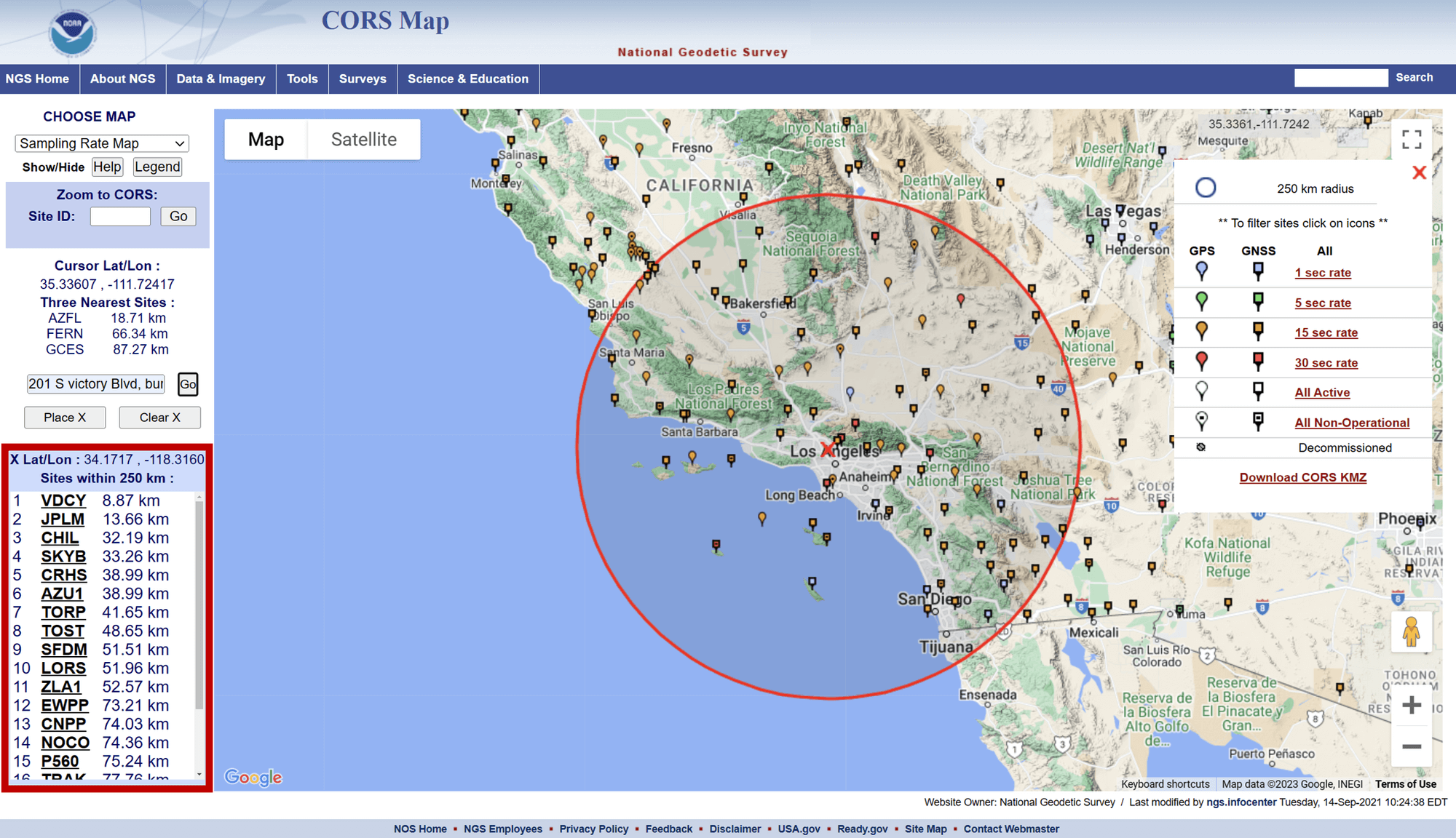
- Go to the NCN website and select NCN Map on the webpage.
- Input the address of the drone flight in the search box on the left and select Go:
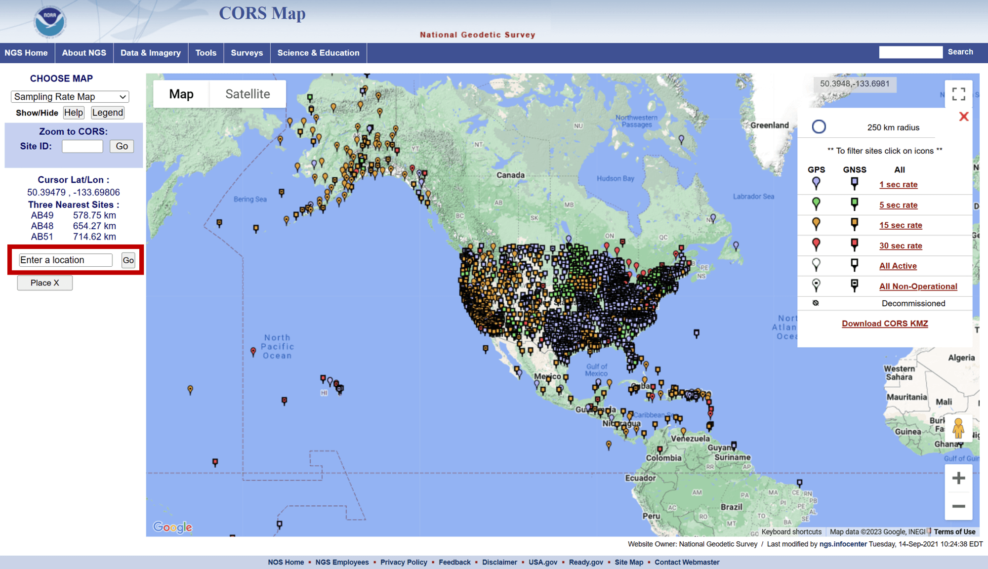
- Select a site with the shortest baseline possible and record the site name. Baseline refers to the distance between the GNSS reference station and the drone. A shorter baseline distance generally results in higher accuracy PPK results, as it reduces the potential for errors introduced by atmospheric conditions and other environmental factors. The baseline distance between the CORS site and the drone can affect the quality of the reference data used for the PPK process. A longer baseline distance can result in more errors due to atmospheric and other environmental factors, which can lead to a less accurate PPK result. Therefore, it is recommended to keep the baseline distance as short as possible while still covering the mapping area. Any sites with a baseline over 20 miles are not recommended to be used.
- Go to the UFCORS website and select the date range for the data you wish to retrieve. Select “get CORS data file” The data will be downloaded as a compressed file (e.g., .zip). It is important to ensure that the CORS data is collected at the same time as the drone image data to ensure accurate PPK processing. You should also carefully evaluate the quality of the CORS data to ensure that it meets the required accuracy standards for the mapping project. Proper planning and execution of the drone mission and CORS data collection are essential to ensure accurate PPK processing and high-quality mapping results.
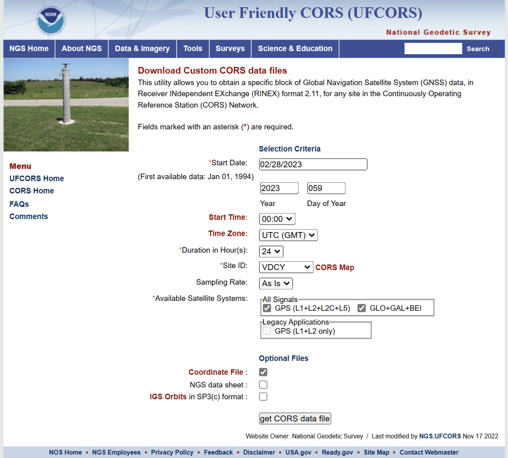
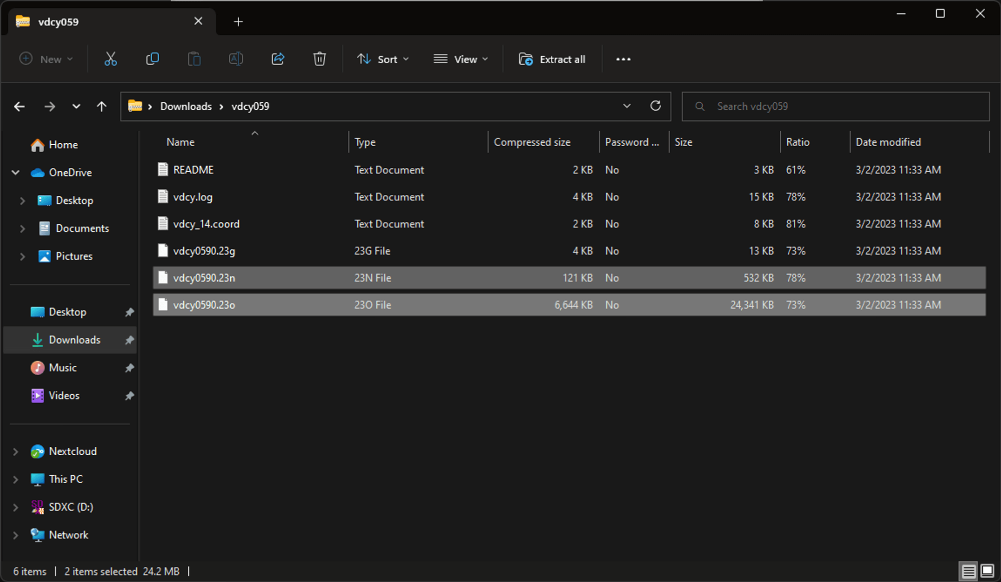
- Open the downloaded zip file and ensure it contains the following two files: X.YYo (Base RINEX file) and X.YYn (Navigation file). Here, 'YY' represents the year number, and 'X' signifies the station site code with the day of the year.
Via DJI D-RTK or Third-party Base Station:
If there is no NGS CORS base station nearby the drone operation site, the DJI D-RTK station might be a good option for obtaining base station data for PPK processing. To use it, simply set up the base station over a known point under WGS84 coordinates (EPSG:4326) and ellipsoidal height in meters. Then, offset the base station location based on the 3D known point coordinate in the Pilot 2 app.
Make sure to set up the D-RTK station onsite first, and wait a few minutes before and after the flight to cover the entire flight duration. Also, avoid moving or tilting the D-RTK station during the drone flight, as it may interrupt data recording due to orientation changes. Once the flight is completed, connect the base station to a computer via a USB-C cable and export the .dat format RTCM files recorded after the flight. By using the DJI D-RTK station, you can avoid the need for additional equipment and subscription fees that may be required for real-time communication. This makes the PPK process more cost-effective and offers greater flexibility for data collection, especially in areas with limited or no cellular coverage.
Step 4. Data Alignment and PPK Processing
Once you have properly prepared all the captured imagery or LiDAR data along with the necessary PPK files — including the drone’s satellite observation data and the rover’s satellite observation data from a reference source — the next step is to align the drone and rover data and begin the PPK processing.
Depending on whether your dataset consists of photogrammetry or LiDAR data, follow the corresponding PPK processing workflow outlined below. If you are not using a DJI Enterprise photogrammetry sensor, the PPK processing workflow remains largely the same. You may refer to the third-party PPK processing guide provided below for reference.
Photogrammetry PPK Process Workflow
Via DJI Terra Software:
- DJI Zenmuse L1 (Visible Photos)
- DJI Zenmuse L2 (Visible Photos)
- DJI Zenmuse P1
- DJI Mavic 3 Multispectral
- DJI Mavic 3 Enterprise
- DJI Matrice 4 E/T/D/TD
*If your camera is not listed above, you can still perform PPK data alignment and processing using third-party PPK software. Please refer to the next section on third party PPK software for detailed instructions.
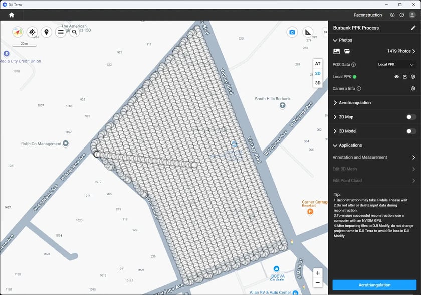
1. With in DJI Terra software, select new reconstruction mission and import all photos. Under the “POS Data” option, select “Local PPK"
Local PPK in DJI Terra
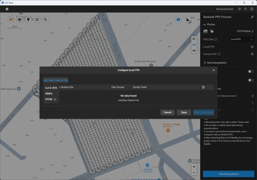
2. Enter the Local PPK Settings and select the "Add Base Station File" option.From here, you can select the base station file in different formats.
- If you used a DJI D-RTK base station to collect the base station files, you will find a
.datfile generated in the D-RTK data directory after connecting the station to a computer via a USB cable. - If you are using a third-party base station or connecting through a CORS network, you can select a RINEX or RTCM file, depending on the satellite observation file format provided by the third-party system.
In this blog, I will use a CORS .YYo RINEX file as an example, select “RINEX”.
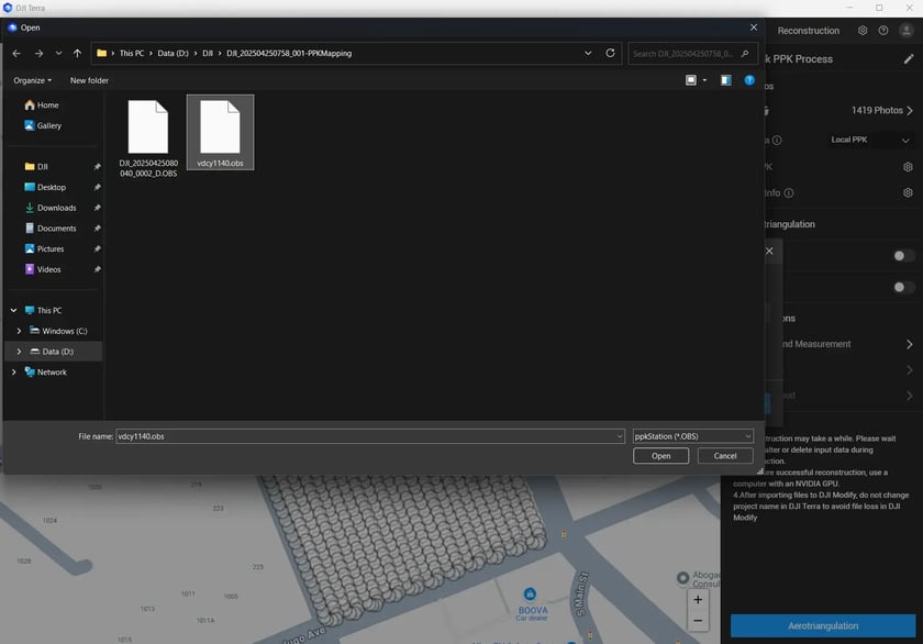
RINEX file selection - DJI Terra
4. Under the "Configure Local PPK" window, define the regional horizontal coordinate system based on the source of the RINEX file.
If you are using a third-party RTK base station, the coordinate system information can typically be found in the station’s settings.
Depending on your region, the observation file may be recorded using different coordinate transformations. For example, in the United States, the horizontal coordinate system is usually based on NAD83(2011) in geographic latitude and longitude, and the vertical reference is typically ellipsoidal height in meter.
Within this window, you can also manually adjust the base station coordinates to correct the base station position based on more accurate or corrected values if necessary.
Once confirmed all fields, select “Start Calculation” to start the PPK process.
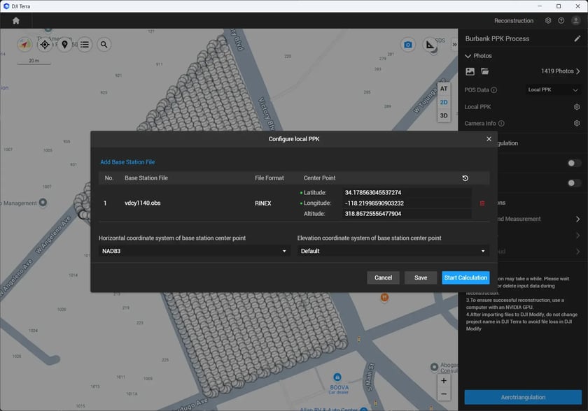
Configure local PPK - DJI Terra
Via Third-party Software:
This section outlines a step-by-step guide for applying drone data together with GNSS rover files collected from sources such as NGS CORS, third-party base stations, or DJI D-RTK stations to initiate the PPK (Post-Processed Kinematic) workflow.
While we recommend using DJI Terra for the PPK process due to its integration and ease of use, DJI does not restrict users from choosing alternative tools they are more familiar with. Users are free to utilize any compatible third-party software for correcting image POS (position and orientation system) data.
In the following section, we will use RedCatch REDToolBox as an example of a third-party solution for PPK image data correction.
- To get started, you'll need to open the RedCatch REDToolBox and select the "PPK & Geotagging" option.
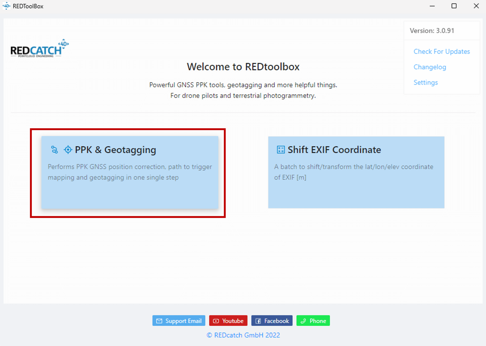
UI - REDToolbox - The option will prompt you to choose DJI as the device option and select PDF quality report and textfile as output formats. Then, select the PPK option as the correction type, and Elliptical height (PPK native) as the output height. After these selections, click on "Next."
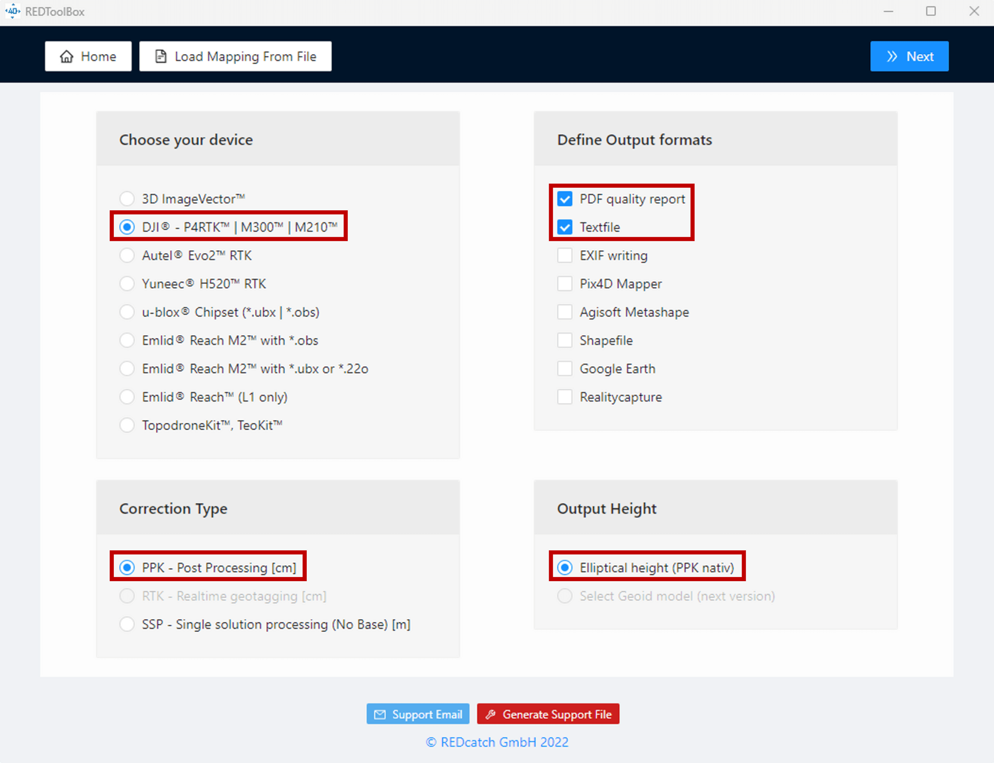
Settings - REDToolbox - To import images, go to the "Import Images" section, and select "Select Images" to define the directory of the raw images. This will ensure that the images are properly imported and can be used in the PPK process.
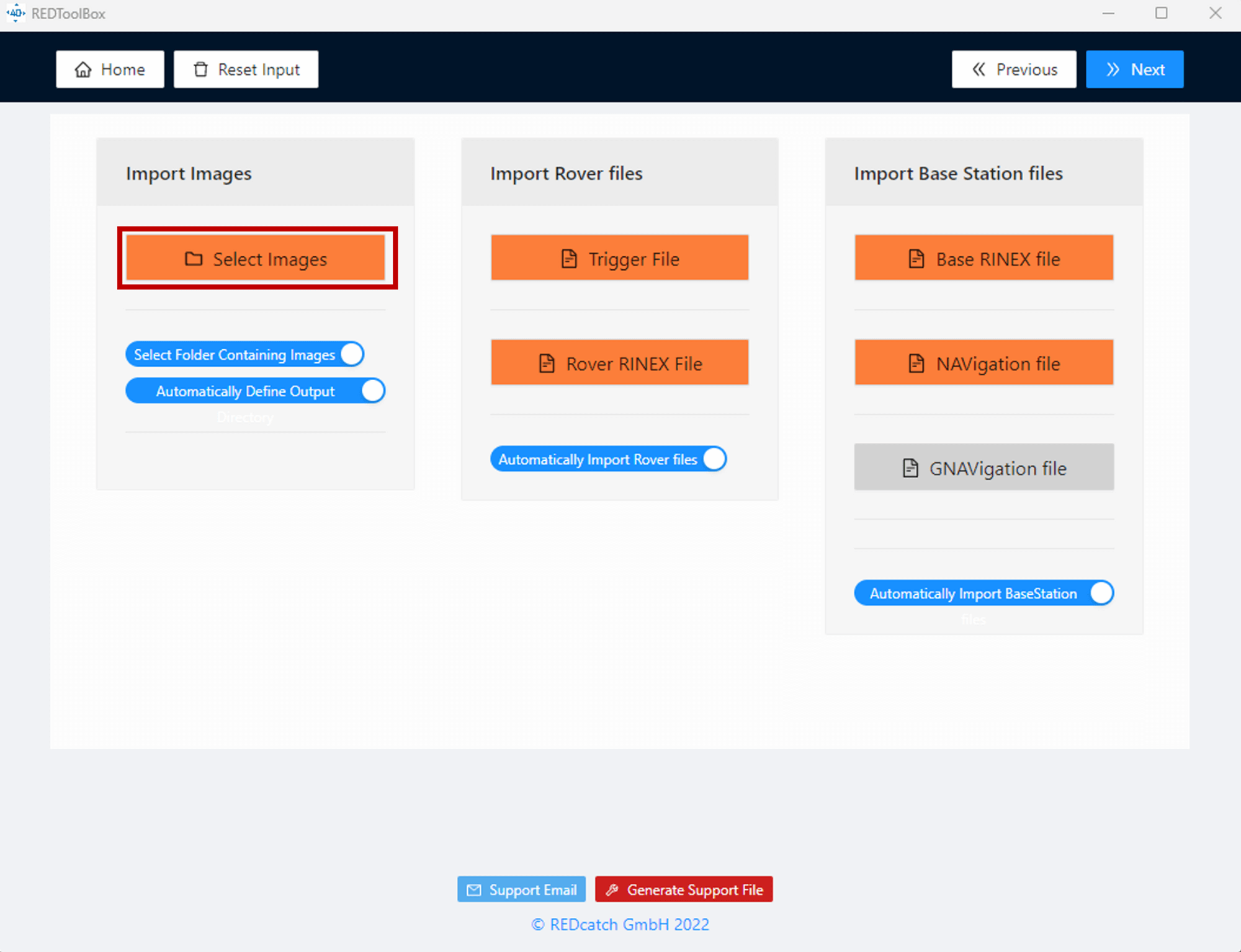
Import Drone Images - REDToolbox - Next, you'll need to select the "Import Rover files" section and choose the "Trigger File" option. Here, you can import the MRK file with the name "XXX_Timestamp.MRK" under the raw image folder. This file will provide important information about the image time stamps that will be used in the PPK process.
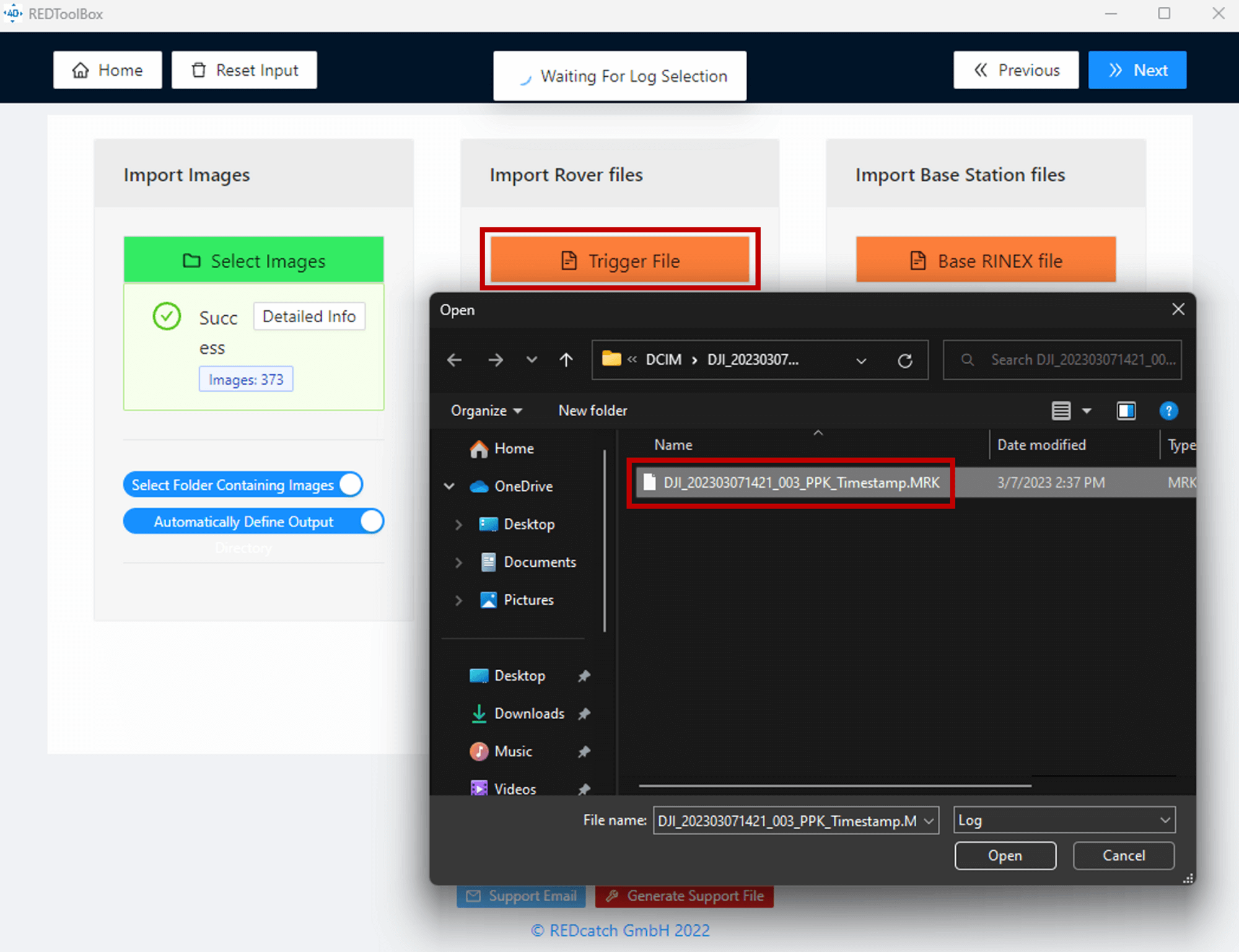
Import Drone Timestamp Data - REDToolbox - After importing the MRK file, you'll need to select the "Rover RINEX file" option once again and import the RINEX file with the name "XXX_PPKRAW.bin" under the raw image folder. Make sure to select the correct file, as this will be critical to the success of the PPK process.
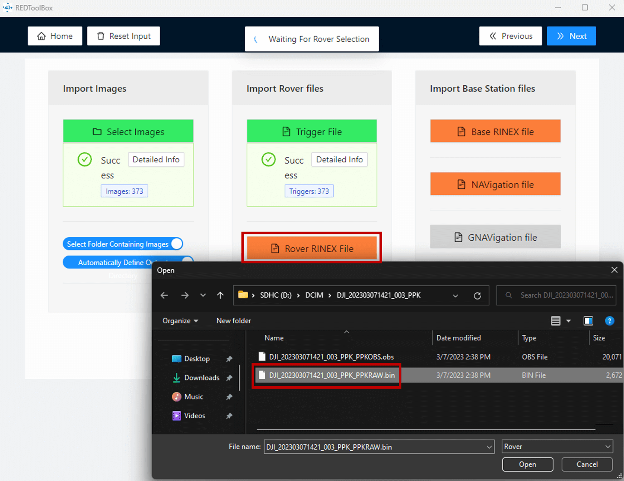 Import Drone RINEX Data - REDToolbox
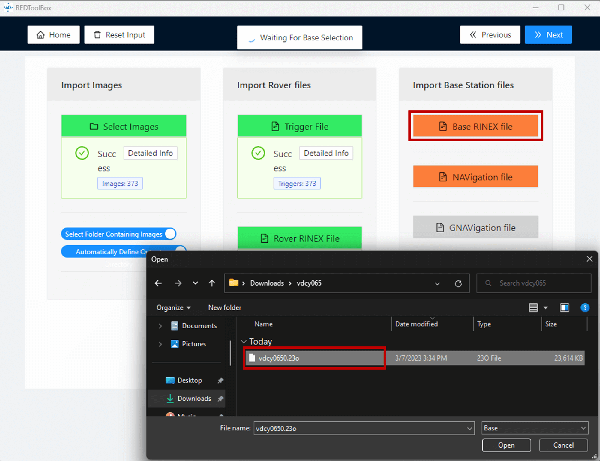
 - Moving on to the "Import Base Station Files" section, select the "Base RINEX file" option and import the RINEX file named "XXX.xxo" from the raw satellite data folder downloaded from the UFCORS site. If you're using the DJI D-RTK 2 Mobile Station for PPK processing, select and import the .dat formatted RTCM file in this option. If you need to merge multiple .dat RTCM files into a single file, use the following tool and run it in the same directory as the multiple RTCM files: merge_bin.bat
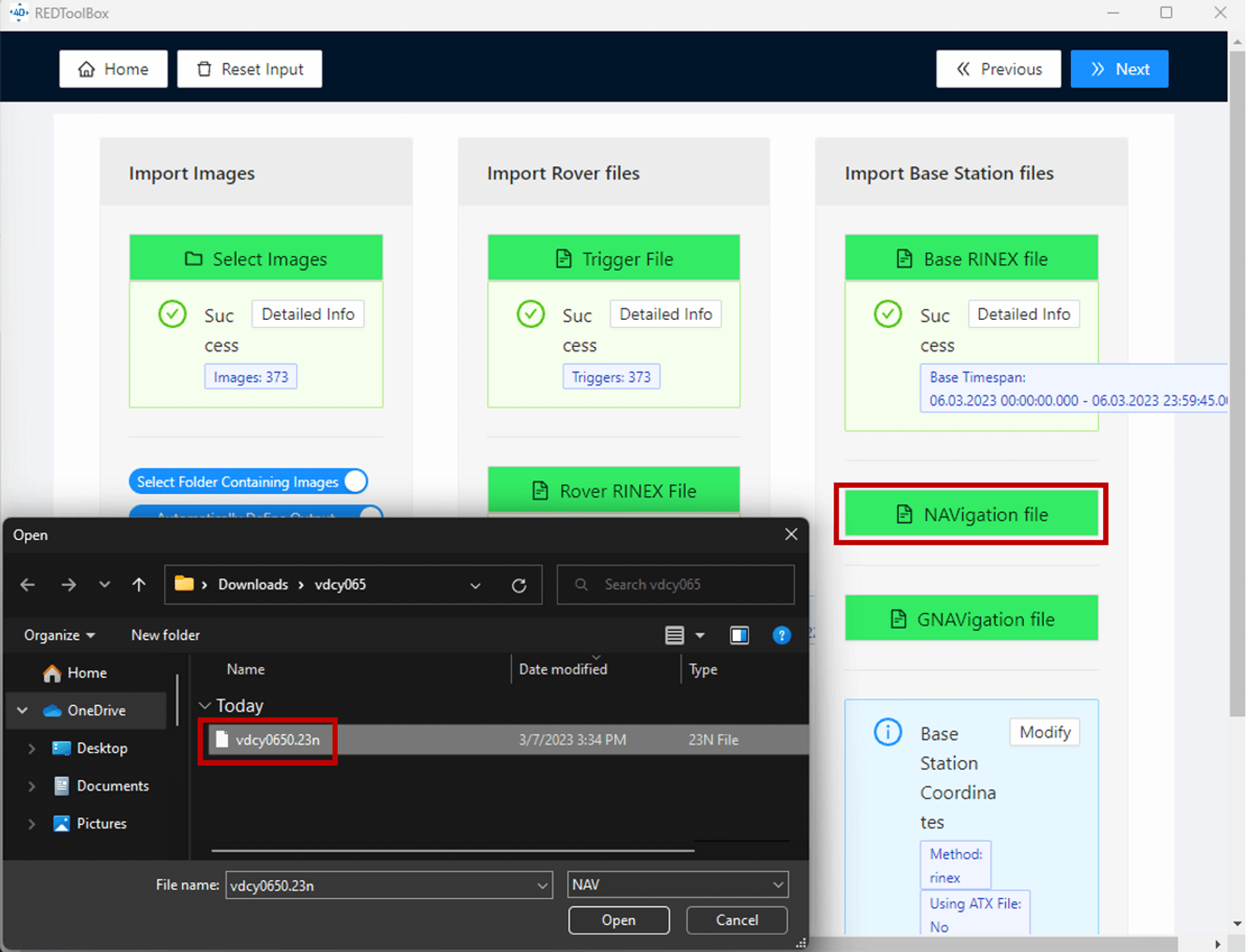
Import Base RINEX Data - REDToolbox - Once you've selected the XXX.xxo file from the raw satellite data folder, the navigation and GNAVigation files should import automatically. If they don't, these two files can be found inside the raw satellite data folder downloaded from the UFCORS site.
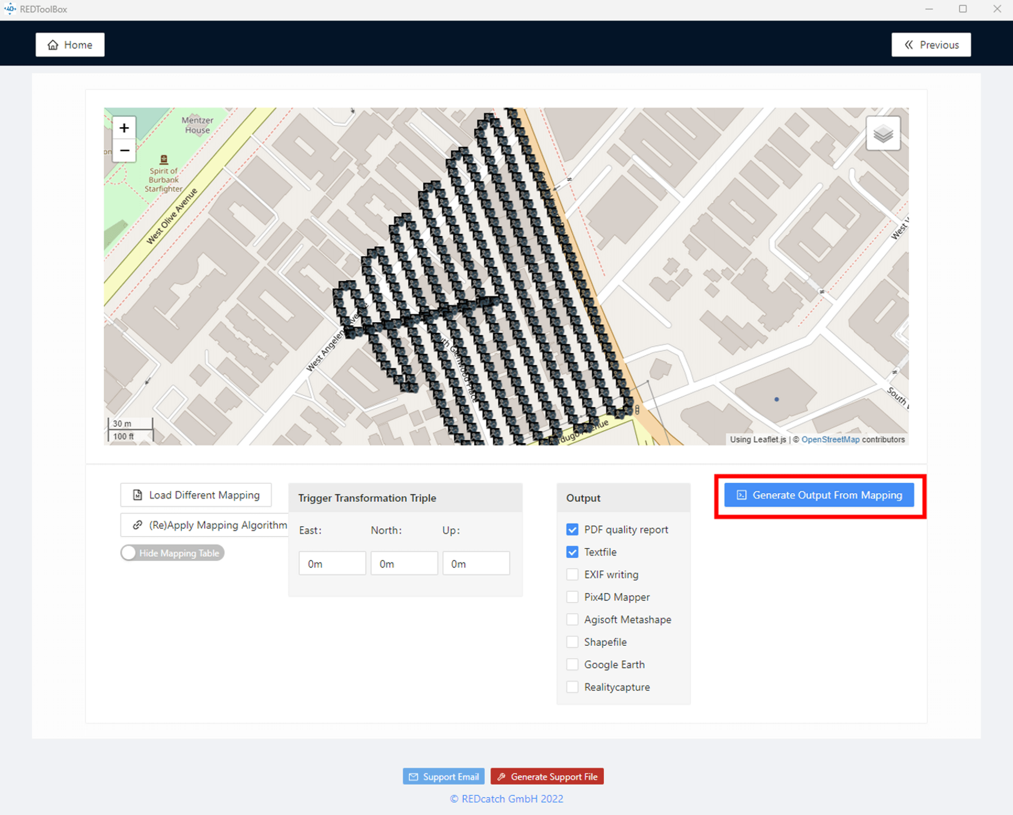
Import Base NAV Data - REDToolbox - Finally, review the mapping summary and select "Execute Mapping" to start the PPK process.
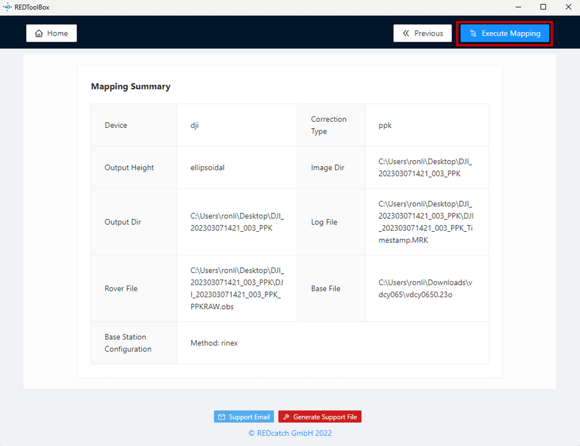
Mapping Summary - REDToolbox - Once the process is finished, check “PDF quality report” and “textfile”, then select the “Generate Output From Mapping” option.
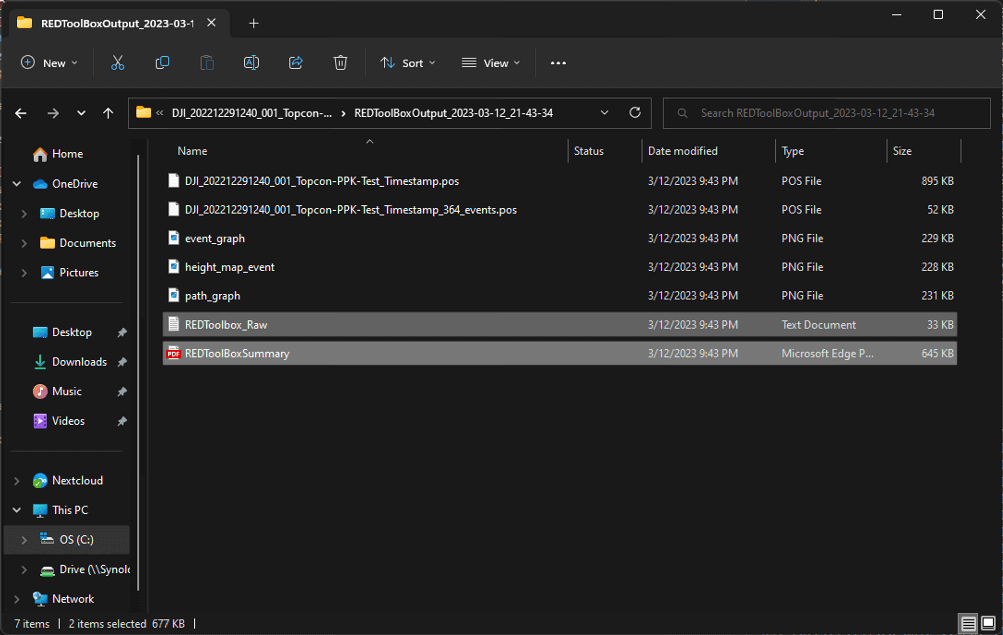
Output POS data - REDToolbox - To ensure that the corrected POS data (REDToolbox_Raw.txt) and summary report (REDToolBoxSummary.pdf) are both exported, open the output folder. Later, we will use the first timestamp file with corrected image POS data for photogrammetry processing.
LiDAR PPK Process Workflow
Before we begin, Please note that only specific LiDAR systems are supported for PPK processing in DJI Terra. If the data is captured with a payload not listed below, they will not be support for PPK processing within the DJI Terra software. Additionally, ensure that the firmware for the LiDAR payload and aircraft is updated to the latest official version before data capture.
Supported LiDAR Systems for PPK Processing:
- DJI Zenmuse L1
- DJI Zenmuse L2
1. To process the DJI Zenmuse L Series LiDAR data using the PPK method, make sure to get the base station reference file prepared first. DJI LiDAR supports the following base station file formats and corresponding version:
| SupportedData Format | Version | Message Type | File name and file suffix need to rename to: |
|---|---|---|---|
| RINEX | V2.1.x | / |
DJI_YYYYMMDDHHMM_XXX.obs
|
| RTCM |
V3.0 V3.2 |
V3.0: 1003, 1004, 1012, 1014 V3.2: MSM4, MSM5, MSM6, MSM7 |
DJI_YYYYMMDDHHMM_XXX.rtcm |
| OEM |
OEM4 OEM6 |
RANGE
|
DJI_YYYYMMDDHHMM_XXX.oem
|
| UBX | / | RAWX | DJI_YYYYMMDDHHMM_XXX.ubx |
It is recommended that the baseline, or distance between the base station used to record the PPK and the aircraft, be within 10km. the base station file used for PPK process must contain the entire LiDAR scan flight duration.
2. Follow the chart above to rename the base station reference file. It is important to rename both the file name and the file extension suffix of the base station reference data correctly. The name of the base station reference file should be identical and match with other LiDAR raw files. For the RINEX file, remember to change the file extension from .YYO to .obs.
3. Ensure that the renamed base station reference file is placed in the same directory as the raw LiDAR data folder. Once this is set up, import the raw LiDAR data folder into DJI Terra to begin processing. DJI Terra will automatically detect the base station reference file and initiate the PPK process using this reference data.
For LiDAR PPK workflows, no additional steps are required. DJI Terra automatically overwrites the POS (Position and Orientation System) data during processing, completing the PPK correction seamlessly.
Step 5. Photogrammetry POS Data Overwrite
In photogrammetry process, the drone image POS data is used in the aerotriangulation process to accurately determine the position and orientation of each image in 3D space. The aerotriangulation process involves computing the relative positions and orientations of the images based on their overlaps and corresponding image features. The drone image POS data is used to compute the orientation of each image in 3D space, and this information is used to generate a sparse point cloud that represents the surveyed area.

Aerotriangulation model generated based on image POS
If the drone’s image POS (Position and Orientation System) data is inaccurate or imprecise, the results of the photogrammetry process will also be compromised. Errors in the POS data can propagate through the aerotriangulation process, leading to inaccuracies during bundle adjustment and ultimately reducing the overall precision of the final outputs.
The accuracy of the image POS data directly affects the global accuracy of the photogrammetric results. The PPK workflow is used to correct these errors — which may stem from GPS drift, noise, or other sensor-related inconsistencies. By applying PPK corrections, you can obtain significantly improved image POS data, which in turn enhances the accuracy of the generated dense point cloud, 3D models, and maps.
In this guide, we will use DJI Terra as an example to demonstrate how to apply and overwrite the image POS data and process the raw photogrammetry dataset.
If you're not yet familiar with the complete workflow, I highly recommend watching the video tutorial I created below:
- Open DJI Terra software, under the “Reconstruction” tab select “New Mission” and then select “Visible Light” to create a new photogrammetry reconstruction mission. After import all the photos, select the “Import POS Data” icon option as shown below.

Import POS Data - DJI Terra - Make sure to import the processed POS file in text format from the last section.

Import POS Data - DJI Terra - After importing the image POS data, a "Format and Properties" window should automatically appear. In this window, adjust the data column and define the column properties under the “Define Data Column” section. Ensure that the first row of the table contains the POS data of the first image, and use the tools under the “File Format” section to define data separators and the first line of the data.

POS Data Format - DJI Terra - To proceed, select the "Known Coordinate System" option under the POS data coordinate system. Then, choose the corresponding horizontal and vertical coordinates for the imported PPK-processed image POS data. It is crucial to select the correct coordinates for both the horizontal and vertical systems to avoid any displacement in output. If you are unsure which coordinate system to choose, you can find the PPK-processed POS data's coordinate system from the PPK software settings or the PPK data process quality report. Typically, the horizontal system should be in WGS84 (EPSG:4326), and the vertical system should be in Ellipsoidal height (in meters, which can be set to Default in DJI Terra). Once you have finished defining the new POS data, select “Import”.
 POS Data Format - DJI Terra
 - To replace the old image POS data embedded in photos with PPK-corrected POS data from the txt file, select "Yes" to confirm the action in DJI Terra. The POS data has now been successfully overwritten.

DJI POS Data Fromat - DJI Terra
Conclusion
Accurate data positioning forms the foundation of high-precision drone mapping and surveying. The PPK workflow corrects positional errors from GNSS data, significantly improving the global accuracy of photogrammetry and LiDAR outputs. Whether using DJI Enterprise sensors or third-party payload systems, knowing how to align and apply corrected POS data is crucial for reliable, consistent mapping results.
With this guide and PPK process tools like DJI Terra, you can process your data confidently to achieve survey-grade results. Remember to verify coordinate system settings, align timestamps precisely, and maintain data integrity throughout the workflow.


-2.png?width=300&name=HS%20-%20Featured%20Images%20(2)-2.png)

